Procedure
Phase 1: Project Setup
The group began by downloading the latest release archive "Zybo-Z7-20-HDMI-2018.2-*.zip" from the repository's releases page. After extracting the contents, they opened the XPR project file located at the extracted location under "/vivado_proj/Zybo-Z7-20-HDMI.xpr" using Vivado 2018.2.
Phase 2: Application Development
The group exported the hardware configuration with the bitstream included by selecting "File -> Export -> Export Hardware" in Vivado. They then launched the SDK, creating a new workspace local to the project. Within the SDK, they created a new application project named "Zybo-Z7-20-HDMI" using the standalone OS platform and targeting the ps7_cortexa9_0 processor.
After selecting the "Empty Application" template, the group imported the source files from the "sdk_appsrc" directory into their project's "src" folder. This provided all the necessary application code to interface with the hardware platform.
Phase 3: Hardware Testing
For the testing phase, the group connected HDMI input and output cables to the board and attached an HDMI-capable monitor. They established a serial connection to the board at 115200 baud using a terminal application to monitor system output.
The group programmed the FPGA using the SDK's "Program FPGA" feature and launched the application on the hardware. The implementation utilized the interrupt-driven architecture visible in the block diagram, where video processing components including the VDMA controller, video timing controllers, and GPIO interfaces triggered interrupts through the concatenation block to the Zynq processing system.
Once running, the application successfully demonstrated the HDMI processing functionality as described in the project documentation.
Code
The code implements a HDMI video demonstration on a Zybo FPGA board, focusing on interrupt-driven architecture. Here's a very short explanation:
The system initializes display controllers, video capture components, and interrupt handlers. It demonstrates various video processing capabilities through a menu-driven interface.
Key components:
- 1.Interrupt handling: The code uses two main interrupt sources (GPIO and VTC) that are concatenated and routed to the processor through an interrupt controller.
- 2.Video buffers: Multiple frame buffers are used to enable frame manipulation while maintaining display continuity.
- 3.Menu interface: Users can select operations like changing resolution, switching frame buffers, applying visual effects (color inversion, scaling), and toggling video streaming.
The interrupt-driven approach allows the system to respond immediately to events like HDMI connections/disconnections without constantly polling device status.
Block Diagram
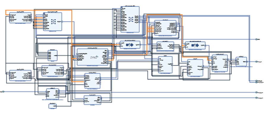
4 peripherals:
- 1.HDMI Input
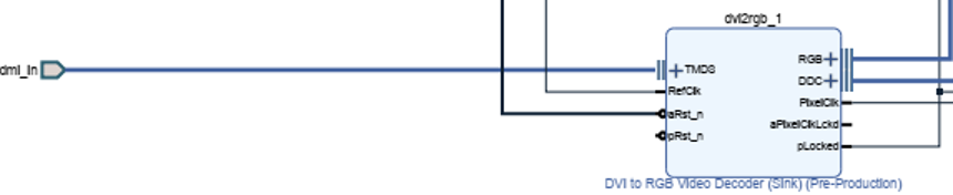
On the left side we have our hdmi_in connected to the TMDS port of our video decoder. The RefClk is connected to the ZynQ FCL_CLK2 and the aRst_n is connected to the peripheral_aresetn[0:0] port of the Processor System Reset.
The right side of the Video Decoder sends RGB decoding signal to the Video In to AXI4-Stream component through the vid_io_in port. The hdmi_in_ddc is going to the DDC port of the DVI to RGB Video Decoder. The PixelClk goes to the clock on the Video Timing Controller. The plocked signal is combined with the AXI GPIO signal to to go to the Processor System Reset under aux_reset_in.
- 2.HDMI Output
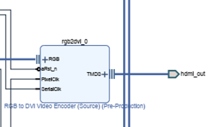
Our hdmi_out is coming from our RGB to DVI Video Encoder. The RGB encoding is connected to the AXI4-Stream to Video out via the vid_io_out port. ARst_n is connected to the Dynamic Clock Generator under the LOCKED_O port. The PixelClk is connected to the Dynamic Clock Generator under PXL_CLK_O. Lastly, the SerialClk is connect to the PXL_CLK_5X_O at the same block as before.
- Zynq Processing System (processing_system7_0)
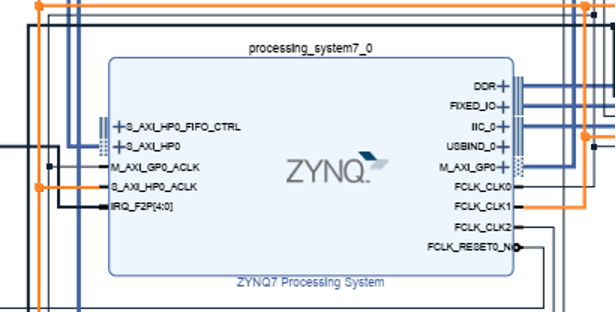
In the center of the board, we have the processing_sytem7_0. It is the part that connects everything together. On the left we connect our AXI Interconnect port to the S_AXI_HP0 port. The M_AXI_GP0_ACLK is more interconnects. The S_AXI_HP0_ACLK takes in video encoders and streams.
On the right the DDR is directly leading to the port. The rest of the ports are clocks and memory access.
- AXI GPIO (axi_gpio_video)
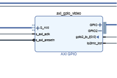
GPIO ports lead to the hdmi_in_hpd. The gpio2_io_I[0:0] leads to the Zynq Processor. The The rest of the ports lead to interconnects and Processor System memory
Interrupt Service
- 1.The processing_system7_0 (ZYNQ7 Processing System) has an interrupt input port labeled "IRQ_F2P[4:0]" - this is the Fabric-to-Processor interrupt line that can receive up to 5 interrupts.
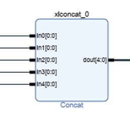
- The xlconcat_0 (Concat) block combines 5 interrupt signals (In0-In4) into a single 5-bit interrupt bus (dout[4:0]), which connects to the IRQ_F2P port of the processing system.
- 3.The interrupt sources appear to be:
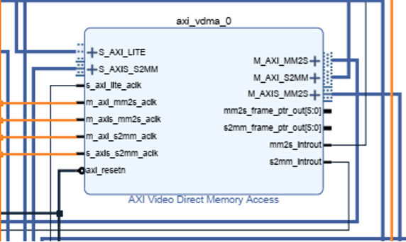
- axi_vdma_0 (AXI Video Direct Memory Access) - has two interrupt outputs:
- i.mm2s_introut (Memory-to-Stream interrupt)
- ii.s2mm_introut (Stream-to-Memory interrupt)
- axi_vdma_0 (AXI Video Direct Memory Access) - has two interrupt outputs:
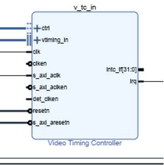
- v_tc_in (Video Timing Controller) - has an irq output
- v_tc_out (Video Timing Controller) - has an irq output
- d.axi_gpio_video (AXI GPIO) - has an ip2intc_irpt output
These interrupt signals are routed to the xlconcat_0 block, which combines them into a single vector that gets routed to the processing system.
The interrupt system enables the processor to efficiently handle events from the video processing components without having to constantly poll their status. For example:
- The VDMA interrupts notify when frame transfers are complete or when errors occur
- The Video Timing Controller interrupts might signal vertical sync events or timing errors
- The GPIO interrupt could signal external events like HDMI hot-plug detection
The processor can handle these interrupts through its interrupt controller, allowing it to respond to these events in real-time without wasting CPU cycles on polling.
Analysis
Just like all the previous labs, in the project we import the file to Viado, and we must confirm that it is the correct version of Viado so that it is compatible. So, in this lab, we use the 2018.2 version of Vivado so we use HDMI Input/Output 2018.2 version of that file. To check if the design is correct, we can click on validate design box on vivado to check if there are no errors with the design. After that, we can use the vivado to run bitstream , load the bitstream to import it to SDK. After importing to SDK, we program the board by clicking on Program FPGA and click on run as on the Zybo Z7-20-HDMI file to run.
Future work
In the future, the HDMI Input/Output multimedia processing could be developed better over this project as the as a better system to develop better HDMI Input/Output. As we all know, technology is constantly evolving, and a better HDMI Input/Output could help with multimedia processing applications. Each generation of HDMI Input/Output delivers higher speeds, better resolutions, lower latency, and greater efficiency. All the software and hardware components of this project would be degraded over time, and that is why we believe that better hardware and software would be developed to improve the components of this project. As FPGA continues to improve it will ensure that we will get a better, smoother and much faster processor version of HDMI Input/output. This will give us an edge in term of developing a software and hardware to be more powerful and stronger for the future
Conclusion
In this laboratory exercise, our group successfully implemented and tested a Zynq-based HDMI video processing system using the Zybo Z7-20 development board. The project demonstrated the practical application of interrupt-driven architecture, where multiple video processing components efficiently communicated with the processing system through concatenated interrupt signals. The implementation followed a systematic approach from project setup through hardware programming and testing. Results confirmed the proper functioning of the HDMI input/output pathways, with real-time video processing capabilities successfully demonstrated. This hands-on experience provided valuable insights into embedded system design, hardware-software integration, and the practical application of interrupt handling in multimedia processing applications.