TL;DR: Antennas are not interchangeable. The type of antenna in your device determines how far it transmits, how much power it draws, whether it plays nicely with regulations, and whether your product actually ships on time. This post breaks down the major antenna types, what makes each one the right tool for a specific job, and how engineers use tools like Smith charts to keep all of it from falling apart.
The Most Overlooked Component in Wireless Engineering
Here's a fact that surprises a lot of people outside the RF world: you can have a perfect radio chip, a perfect PCB layout, and a perfect software stack - and still have a product that doesn't work because the antenna was wrong.
An antenna isn't just a wire sticking out of your device. It's a precision-tuned transducer that converts electrical signals into electromagnetic waves and back again. Every physical dimension, every surrounding material, every nearby metal component affects how it performs. The margin for error is measured in millimeters.
This matters for anyone building connected products: IoT devices, medical wearables, defense systems, consumer electronics, automotive telematics, anything with wireless communication. The antenna decision happens early in the design process and the consequences of a bad one show up at the end, right when you can least afford them.
What follows is a breakdown of the major antenna types used in modern engineering: what they are, how they work at a conceptual level, and where they show up in the real world.
The Dipole Antenna: The Ancestor of Everything
If antenna types had a family tree, the dipole would be at the root.
A dipole antenna is two conductive elements - typically two rods or wires - aligned on the same axis and fed from the center. At half-wavelength, the antenna reaches resonance, meaning it naturally oscillates at the target frequency with maximum efficiency. The half-wave dipole is the benchmark against which every other antenna's gain is measured.
Think of it like a tuning fork for radio waves. When you strike a tuning fork at the right frequency, it rings perfectly and efficiently. A half-wave dipole does the same thing electromagnetically.
Where you see it: Dipoles show up in FM radio antennas, television antennas, ham radio setups, wireless access points, and as the reference element inside more complex antenna arrays. The "rabbit ears" on older televisions were literally two dipole elements you adjusted by hand until the signal was clean.
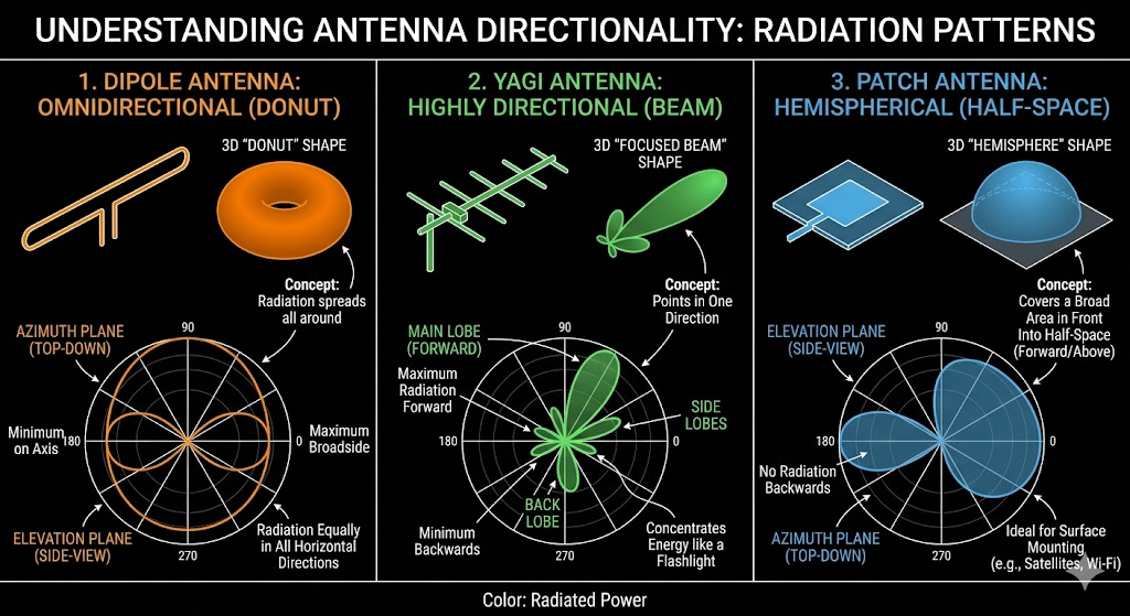
Why engineers care: The dipole's radiation pattern - a donut shape in free space - makes it ideal when you need roughly equal coverage in all directions on a horizontal plane. It's also the simplest antenna to model theoretically, which makes it an essential teaching and calibration tool.
Business relevance: If you're hiring RF engineers or reviewing antenna-related proposals, the dipole is the baseline. An engineer who can't articulate dipole fundamentals hasn't earned the more complex work yet.
The Monopole Antenna: Half a Dipole, Twice the Headaches
Take a dipole, cut it in half, and mount the remaining element over a ground plane. That's a monopole.
The ground plane - whether it's a metal chassis, a PCB, or the earth itself - acts as a mirror, creating an image of the missing half electrically. The result is an antenna that behaves like a full dipole but only requires half the physical length.
Where you see it: Car radio antennas are the classic example — a single rod mounted on the metal roof of the vehicle, where the roof acts as the ground plane. Cell tower base antennas, walkie-talkies, and the rubber duck antennas on two-way radios are all monopole variants. The stubby antenna on your router? Monopole.
The catch: A monopole's performance is only as good as its ground plane. A small, irregular, or improperly designed ground plane degrades efficiency fast. This is why antenna placement on a PCB is a major engineering decision - moving the antenna by a few millimeters relative to other components changes the effective ground plane geometry and can shift the resonant frequency enough to cause failures in regulatory testing.
Business relevance: When your engineering team says they need to revisit the PCB layout because of the antenna, this is usually why. It's not a mistake - it's the physics.
Key Insight: The monopole is everywhere because it's compact and inexpensive. But "simple" doesn't mean "easy to implement." A badly placed monopole in a production device is one of the most common reasons wireless products fail FCC certification on the first submission.
The Loop Antenna: Quiet, Compact, and Stubborn About Noise
Where dipoles and monopoles respond primarily to the electric field component of a radio wave, a loop antenna responds to the magnetic field. This distinction is more important than it sounds.
A loop antenna is exactly what it sounds like - a conductor formed into a closed loop, either circular, square, or rectangular. Small loops (much smaller than a wavelength) have a figure-8 radiation pattern with deep nulls in the plane of the loop. Large loops (close to a wavelength in circumference) approach the behavior of a full-size dipole.
Where you see it: Loop antennas are common in AM radio receivers - the ferrite bar antenna inside a tabletop radio is a small loop. RFID readers use loop antennas to inductively couple energy to RFID tags at close range. Near-field communication (NFC) in smartphones - the feature you use for contactless payments - is built on loop antenna principles. Many smartwatches and fitness trackers use loop antennas to fit a functional antenna into a curved form factor.
The magnetic field advantage: Because loops are primarily sensitive to the magnetic component of a wave rather than the electric component, they naturally reject a lot of electrical noise - the kind generated by motors, power lines, and switching power supplies. This makes them well-suited for electrically noisy environments where other antenna types would be overwhelmed by interference.
Business relevance: Any product that needs to function reliably in an industrial environment - factory floors, medical equipment near other electronics, automotive systems - should have a serious conversation about whether a loop antenna belongs in the design. The noise immunity is a genuine competitive advantage in those contexts.
The Yagi-Uda Antenna: Directional Power Done Right
The Yagi-Uda antenna (usually just called a Yagi) looks like a TV antenna on a roof - and that's exactly what it is, in the most famous application.
A Yagi consists of a driven dipole element, a reflector element behind it, and one or more director elements in front of it. The parasitic elements (reflector and directors) aren't connected to the feed line - they work by mutual electromagnetic coupling, reshaping and focusing the radiation pattern into a tight beam pointed in one direction.
More directors equals more gain equals narrower beam. A five-element Yagi gets you 8–10 dBi of gain over a simple dipole. Add more elements and you push that further, at the cost of a physically longer antenna and a beam so narrow you have to point it precisely.
Where you see it: Rooftop TV antennas, Wi-Fi directional antennas for point-to-point links between buildings, amateur radio long-distance communication, radar systems, and wildlife tracking equipment where you need to follow a tagged animal with a directional beam.
The tradeoff: A Yagi trades omnidirectional coverage for focused range and gain. You get more signal in one direction and essentially nothing in the others. That's perfect for a fixed point-to-point link and completely wrong for a device that needs to communicate with sources in any direction.
Business relevance: When someone on your team proposes a Yagi for a product, the right question to ask is: do we know exactly where our signal source is at all times? If the answer is yes, a Yagi is powerful and cost-effective. If the answer is "mostly," you're going to have field reliability problems.
The Patch (Microstrip) Antenna: The One That Made Wireless Products Slim
This is the antenna type most responsible for why your phone is thin.
A patch antenna - also called a microstrip antenna - is a flat rectangular or circular conductor printed on a dielectric substrate with a ground plane on the other side. The whole structure is a few millimeters thick. It radiates from the edges of the patch, producing a hemisphere-shaped beam pointed away from the ground plane.
Where you see it: GPS receivers in every device with location capability, Wi-Fi antennas in laptops and tablets, cellular antennas in smartphones, radar sensors in modern vehicles, and the flat antennas on satellite communication terminals. If you've seen a modern satellite internet dish - the kind that lies flat on a roof instead of pointing at a dish reflector - it's a phased array of patch elements.
The engineering appeal: Patch antennas can be manufactured using the same PCB fabrication process as the rest of the circuit. No special manufacturing step, no separate component to source, no mechanical assembly. The antenna is literally printed into the board. For consumer products at scale, that's a significant cost and supply chain advantage.
The engineering challenge: Patch antennas are naturally narrowband. They're efficient over a fairly small range of frequencies, and the substrate material, patch dimensions, and ground plane size all affect where that range sits. Getting the design right requires careful simulation and usually multiple prototype iterations.
Business relevance: If your product needs GPS, Wi-Fi, Bluetooth, or cellular in a thin form factor, patch antennas are almost certainly in the design. The time and cost in your schedule for antenna tuning iterations is normal and expected - it's not a sign the team doesn't know what they're doing. It's the process working correctly.
The Horn Antenna: When You Need a Serious Beam
A horn antenna is a waveguide - a hollow metal tube that guides electromagnetic waves - that flares out at the end like a trumpet or a megaphone. The flaring is what gives it directional gain and controls how the beam spreads.
Horns are used at high frequencies - microwave and millimeter-wave bands - where wavelengths are short enough that a compact, flared metal structure can produce significant gain. They're one of the most efficient antennas available at these frequencies, with well-understood, predictable behavior that makes them valuable both as practical antennas and as measurement tools.
Where you see it: Radar systems, satellite ground station feeds, point-to-point microwave backhaul links, 5G millimeter-wave base stations, radio astronomy equipment, and antenna test chambers where horn antennas are used as reference sources because their gain and pattern are so well characterized.
The context of 5G: Millimeter-wave 5G - the version that delivers multi-gigabit speeds - operates at frequencies between 24 GHz and 100 GHz. At those frequencies, horn antennas and horn-based phased arrays are one of the primary tools for delivering high-gain directional beams. The speed you see advertised for 5G mmWave is partly a story about horn antenna engineering.
Business relevance: If your product or your client's product touches radar, satellite communication, or mmWave 5G, horn antenna expertise is a specialized and genuinely rare skill set. It's worth asking specifically about during technical interviews.
The Phased Array: The Antenna That Changed Everything
A phased array isn't a single antenna type - it's an architecture. It's a grid of antenna elements (often dipoles, patches, or slots) where the signal to each element can be shifted in phase independently, creating a beam that can be electronically steered in any direction without any moving parts.
Think of it like a stadium wave. When the fans in a stadium do the wave, they each stand up at slightly different times, and the apparent motion moves around the stadium. A phased array does the same thing with electromagnetic waves - by controlling the timing of each element's transmission, the combined wave front can be aimed precisely at any angle.
Why this matters: Traditional directional antennas need a physical pointing mechanism - a servo motor, a gimbal, a rotation platform. That adds weight, cost, maintenance requirements, and failure points. A phased array steers electronically, in milliseconds, with no moving parts.
Where you see it: Modern military radar, the F-35's radar suite, the Starlink satellite dish on your roof, cellular base station beamforming for 4G and 5G, airport surveillance radar, and weather radar systems. The flat Starlink terminal is a phased array of thousands of antenna elements that tracks a moving satellite across the sky by electronically steering its beam in real time.
Business relevance: Phased array engineering is one of the most demanding and highest-value specializations in RF engineering. Teams that can design, simulate, fabricate, and calibrate phased arrays are in short supply. If you're hiring for a defense, satellite, or 5G infrastructure project and the job description includes phased arrays, expect the talent search to be competitive and the compensation to reflect that.
Reading the Smith Chart: The RF Engineer's Compass
Now we get to the tool that ties all of this together in the real world.
A Smith chart looks like a circular graph covered in overlapping curves. To the uninitiated, it looks like modern art designed by someone who hates you. To an RF engineer, it's one of the most information-dense visualization tools in the field.
What problem does it solve?
Every antenna has an impedance - a combination of resistance and reactance that characterizes how it interacts with the signal source feeding it. For maximum power transfer, the antenna's impedance needs to match the impedance of the transmission line and the rest of the circuit (almost always 50 ohms in modern RF systems). When they don't match, power reflects back from the antenna instead of radiating. That reflected power is wasted, heats up components, and in high-power systems can damage the transmitter.
Getting to a good impedance match - especially across a range of frequencies - requires a matching network: a small circuit of inductors and capacitors (or transmission line sections) that transforms the antenna's natural impedance to the desired 50 ohms.
The Smith chart is the tool engineers use to navigate that transformation visually.
How it works conceptually:
The center of the Smith chart represents a perfect 50-ohm match - zero reflected power, all signal going where it should. Every other point on the chart represents a different impedance value. Moving along the circular curves corresponds to adding capacitance or inductance to your matching network. Moving along the arcing curves corresponds to adding transmission line length.
An engineer plots the antenna's measured impedance on the chart, then traces a path along the curves - adding a component here, adjusting a line length there - until they reach the center. Each step on the chart corresponds to a real component in the matching network.
Why this matters at a business level:
Impedance matching is not optional. It's the difference between an antenna that radiates efficiently and one that reflects most of the transmitted power back into the amplifier. A poorly matched antenna wastes battery, heats up components, reduces range, and potentially fails regulatory power efficiency tests.
When your RF team says they're doing "matching network optimization," they are sitting in front of a Smith chart (or its software equivalent in tools like Keysight ADS or Ansys HFSS) doing exactly what's described above. The time they're spending is directly tied to the efficiency and battery life of the final product.

Why Antenna Selection Is a Business Decision, Not Just a Technical One
Here's the part that doesn't show up in engineering textbooks.
Every antenna type involves tradeoffs between size, bandwidth, gain, directionality, cost, and integration complexity. None of those tradeoffs are purely engineering decisions - they have schedule, cost, and product implications that belong in business conversations.
| Antenna Type | Typical Application | Key Tradeoff |
|---|---|---|
| Dipole | Reference, base stations, legacy systems | Size vs frequency; lower frequencies mean longer elements |
| Monopole | Mobile devices, routers, handheld radios | Ground plane quality determines everything |
| Loop | RFID, NFC, AM recievers, wearables | Excellent noise reduction, limited range at small size |
| Yagi-Uda | Point-to-point links, TV reception, tracking | High gain but narrow beam, requires precise pointing |
| Patch/ Microstrip | GPS, Wi-Fi, cellular, automotive radar | Low profile and PCB-compatible, but inherently narrowband |
| Horn | Radar, satellite feeds, mmWave 5G | High efficiency and predictability, requires waveguide infrastructure |
| Phased Array | 5G, defense radar, satellite terminals | Electronically steerable, no moving parts. Complex and expensive |
An experienced RF engineer doesn't just know which antenna works - they know which antenna works given your form factor, your frequency band, your target cost, your regulatory requirements, and your manufacturing process. That judgment is what separates a senior hire from a junior one in this field.
Conclusion: The Antenna Is a System, Not a Component
The biggest misconception about antenna engineering is that the antenna is a single, isolatable component that you drop into a design late in the process. It isn't.
The antenna is a system that interacts with the PCB, the enclosure, the human hand holding the device, the nearby components, and the electromagnetic environment the product will operate in. Design decisions made in month one - about enclosure materials, component placement, ground plane geometry - determine what antenna options you have in month six.
Companies that treat antenna engineering as an afterthought pay for it in certification failures, design respins, launch delays, and products that don't meet their range or battery life specifications in the field.
Companies that bring antenna expertise in early, give it a seat at the architecture table, and invest in proper simulation and prototyping tools consistently build better wireless products faster.
That's not a technical opinion. That's a business outcome.
FAQ
What's the most common antenna for consumer Wi-Fi devices? The monopole and its variants (including the printed inverted-F antenna, or PIFA) dominate smartphone and tablet designs because they're compact, PCB-compatible, and can be tuned to cover multiple frequency bands. Routers typically use external dipoles or monopoles for their familiar adjustable antenna appearance.
What does "antenna gain" actually mean? Gain describes how concentrated an antenna's radiation is in a particular direction compared to a reference antenna (usually the isotropic radiator or the dipole). Higher gain doesn't mean the antenna generates more power - it means it focuses the same power into a narrower beam, delivering more intensity in the targeted direction. Think of a flashlight vs. a light bulb: same power, very different direction.
Why do some products have multiple antennas? Multiple antennas serve different purposes: covering different frequency bands (a phone might have antennas for cellular, Wi-Fi, Bluetooth, GPS, and NFC), enabling MIMO (Multiple Input Multiple Output) for higher data throughput by using spatial diversity, or providing redundancy. Each antenna requires its own matching network and careful placement to avoid coupling between elements.
What does a Smith chart show that other tools don't? A Smith chart displays impedance across the full complex plane - both the resistive and reactive components - in a normalized circular format that maps directly to how matching networks transform impedance. It lets engineers visualize the path from a measured impedance to a target match, understand bandwidth behavior, and design matching networks graphically. Software tools have made automated impedance matching easier, but the underlying Smith chart framework is still how most RF engineers think about and communicate matching problems.